The American Concrete Pipe Associations precast concrete box section program was implemented to develop a product for these applications and to. Based on the indicated input values the spreadsheet will calculate the minimum required pipe culvert diameter and the headwater depth for the next.
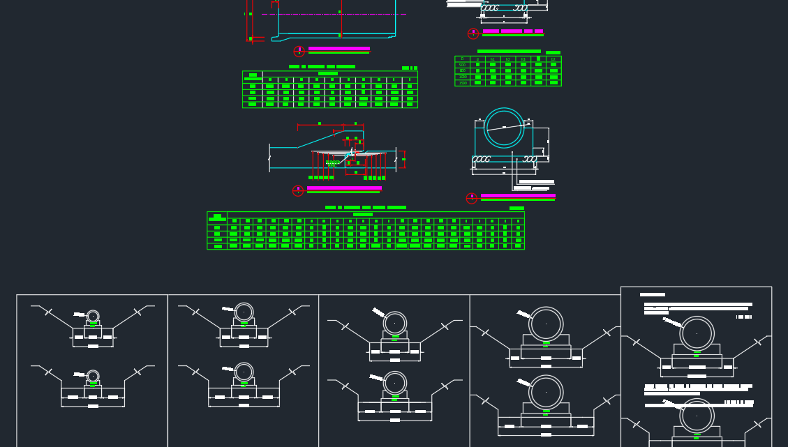
Pipe Culvert Details Autocad Drawing
An Example Culvert Design.
. Velocity of flow through pipe. 3 If a FALL is used upstream of the face extend the barrel invert slope upstream from the face a distance of D2 before sloping upward more steeply. Use type 3 transition Fig.
The following design example is for the wet extended detention ED pond from STP Group 1 stormwater ponds. 3 7 6 w 6 6 B ft L ft inches t inches H ft Page 28 Design Example Pipe Friction. Using HY-8 to Design Culverts LETS TRY A DESIGN EXAMPLE.
DESIGN OF PIPE CULVERT. Cast-in-place reinforced concrete box culverts have been designed and used for many years because of special waterway requirements unusual load conditions or designer preference. Culvert Extension - A portion of a culvert built beyond the limits of a previously existing culvert.
4 Culver Design Example 4 we will do this now Open up Culvert Design Example 4 packet and PowerPoint file. The actual headwall extension dimensions shall be determined to suit the project specific culvert dimensions. Round Pipe and Corrugation Terminologies- Figure 91 shows the terminology commonly used in describing round pipe.
Learn the equations to use when calculating design for both inlet and outlet. Inlet type As the drainage channel is poorly defined and the upper canal bank is only 4 ft higher than channel invert a type 3 or 4 inlet transition will be good. If USGS data are not available for a particular culvert location flow quantities may be determined by the Rational Method or by statistical methods using records of flow and runoff.
D is the inside height of the pipe culvert in fr m for si. The design life of a rigid pipe shall be 120 years. Categories of structural behavior.
Erosion Erosion around the culver or adjoining area could lead to failure of the culverts. Headwater depths water surface elevations WSELs and flow rates Q for the. DESIGN OF PIPE CULVERT 10 20 DATA Discharge through pipe culvert 157 cumsec Velocity of flow through pipe 200 msec Width of road 750 m Bed level of flow H1 100 m Top level of embankment H2 103 m Wheel load 6250 kN Impact factor AxV 150 DIAMETER OF PIPE Discharge 4 x d2 x V d 100 m.
Either the flow rate through the culvert is controlled by the inlet to the pipe or the flow rate through the culvert is controlled by the outlet from the culvert. Other designs are more complex where structural hydraulic environmental or other considerations must be evaluated and provided for in the final design. Impact factor AxV.
A spreadsheet screenshot for pipe culvert design calculations The Excel spreadsheet screenshot below shows part of a spreadsheet for circular culvert design calculations based on inlet control. Top level of embankment. Mannings n 0024.
These culverts involve the construction of super structure in the form of arches. Inlet control and outlet control are the two main approaches used for pipe culvert design. The arch culverts are not provided with the piers and batters to the sides of aboutment.
A Calculated byVN Date032015 STRUCTURAL DESIGN OF CULVERT TO BS EN 1295-1 Note. Bed level of flow. Box Culvert - A culvert in the shape of an enclosed rectangle and consisting of a bottom slab two wall elements and a top slab.
Designer - Individuals designated by the Structural Engineer to use this manual to design and detail culverts. Culverts diameter or height greater than 1200. Q is the design discharge through the culvert in cfs m3s for si.
When the area around it is eroded part of the structure will settle leading unbalance conditions. Pipe Culverts Page 27 Design Example Inlet Type 3. Adopt RCC NP3 heavy duty non pressure pipe for carrying.
The minimum diameter of culvert pipes under a main roa dway shall be 18 inches. Hw is the headwater depth above the invert at the inlet in ft m for si. DIAMETER OF PIPE Discharge 4 x d2 x V d.
A is the cross-sectional area of the culvert in ft2m2for si. For example we increase the thickness of the pipe by 1mm than it is required by the design. An example of a rigid pipe is a reinforced concrete pipe.
Roadside Drainage Ditch Aroadside drainage ditch primarily conveys roadway runoff. The following colour key is a guide to using the full calculation page. INPUT DTATA COMPUTED OUTPUT DATA TO BE CHECKED STANDARD DATA Assumptions.
Some culvert designs are relatively simple involving a straight-forward determination of culvert size and length. These values may vary from standard to standard. The minimum depth of cover required for a pipe culvert is a function of the pipe type eg.
It may also convey offsite flows so the designer should be aware of where water is coming from that shows up in the roadside ditch. Figure 92 depicts a profile of a corrugated pipe 3 in by 1 in corrugation with terminology and sample dimensions. Based on the specific criteria.
Design a concrete culvert using the procedures given by the USBR Design of Small Canal Structures USBR 1978 The culvert will go underneath a concrete-line canal as shown in the figure below perpendicular to the canal alignment shortest path across The outside slope of the canal banks is 11 on both sides HV. Using HY-8 to Design Culverts Selecting a Proposed Shape Pipe Culvert Interior Designation Smooth Interior. The following design criteria should be considered for all culvert designs as applicable.
The are similar to the Masonry bridges. Mannings n 0012 Corrugated Interior. Concrete or steel dead and live loading and in the case of concrete pipes the class of pipe.
Figure 91 Terminology used in describing round pipes. 2 Wingwall flare angle range from 15-degrees to 26-degrees with top edge beveled or from 26- degrees to 90-degrees with or without bevels Figure IV-11. Design Draw a Pipe Culvert with 3 vents Examples Part 1 - YouTube.
The following sections discuss each of the above criteria as it relates to culvert siting and design. In this video we will learn how to design and draw a pipe culvert with 3 vents for section elevation and Plan half earth removed sectionsIf you have. A cast in- situ headwall extension with minimum thickness as specif ied in the standard drawing 1243 Drawing 2 and 3 shall be used to connect the precast headwall and the pipe or box culvert.
When determining the cover the distance from the finished road surface to the crown of pipe collar should be used. Culvert pipe under roadway approaches ie driveway shall have a minimum diameter of 12 inches. The slab culverts are constructed for a span of maximum 25 m in width.
The parameters in the equation are as follows. DATA Discharge through pipe culvert. The design of a culvert should take into account many different engineering and technical aspects at the culvert site and adjacent areas.
2

What Is Culvert Types Materials Location And Advantages Engineering Discoveries In 2022 Culvert Concrete Shipping Container House

Culvert What Is A Culvert Types Of Culvert Culvert Meaning Parts Of Culvert Arch Culvert Box Culvert Civiconcepts
2

Concrete Box Culvert Design Spreadsheet Culvert Design Concrete Design

Culvert Hydraulics Basic Principles

Pipe Culvert Design Pdf Concrete Engineering

Design Draw A Pipe Culvert With 3 Vents Examples Part 1 Youtube
0 comments
Post a Comment